Wouldn’t it be great to have a printer that was connected to the mains just when needed, and disconnected when not? With a wireless connection? And AirPrint? Well, here’s how to turn virtually any printer into such a device, with the help of a Raspberry Pi.
DISCLAIMER: Use at your own risk, no warranty whatsoever. Be extra careful, electricity could kill you.
Revision: 2016-04-21
Audience
The following instructions are targeted at experienced users. You may always feed a search engine with terms like “Raspberry Pi topic” (Raspberry Pi WLAN client, for example) in order to complete each step.
Objective
Learn how to turn the single-board computer Raspberry Pi into a always-on low-power networked print server. The special feature is, your printer will be automatically connected to and disconnected from the mains as needed.
Prerequisites
You need:
1. Some printer…
- supported by CUPS (the Common Unix Printing System)
- preferably with built-in PCL or PostScript capabilities
- preferably a laser printer, their toner wouldn’t dry out
2. LAN or WLAN
- so your devices can connect to each other
- and hand over print jobs
3. Raspberry Pi with…
- WLAN (Wireless LAN, Wi-Fi) adapter or LAN cable, to connect to your (W)LAN
- a USB or a Ethernet cable, to connect the Raspberry Pi physically to your printer
- a relay, so you can switch deadly electricity on/off without killing yourself or your devices
- a computer power chord to cut open and connect to the relay
- a small breadboard and a few Dupont female/male cables (or soldered cables)
- a sensor button and a resistor, for manual operation of the relay
- a LED and a resistor, so the Pi won’t fry it, to indicate the state of system
- a RTC (Real Time Clock), so the time is always accurate, as is good practice for all servers
- a Linux OS such as Raspbian jessie, as used here for all the instructions
- a few scripts to control the operations
Setup Instructions
These instructions cover a Raspi WLAN client system, serving a printer named standard to your LAN.
General Setup
- Boot your Raspi into Raspbian jessie.
- Log on
- Become root permanently:
sudo -s - Connect your printer to Raspi via USB or LAN cable, and turn it on.
- Connect the WLAN adapter, then connect to your router in the client role. The IP address of the Raspberry Pi will hence be referred to as $RASPI_IP.
CUPS Setup: The Server and a Printer Named standard
- Install CUPS (print server) and Avahi (MDNS/ZeroConf/Bonjour) with all the depencies (thanks, Debian!):
apt-get install cups cups-bsd avahi-utils - Note: You can download etc_cups_cupsd.conf.tar.gz (md5sum 671bb1dadff6183a24c227ab509ff8f3; install with tar -C / -xvzf etc_cups_cupsd.conf.tar.gz), which contains the changes described below.
Edit the upper part of /etc/cups/cupsd.conf to:
LogLevel warn
MaxLogSize 0
Port 631
ServerAlias *
Listen /var/run/cups/cups.sock
Browsing On
BrowseLocalProtocols CUPS dnssd
BrowseOrder allow,deny
BrowseAllow all
BrowseRemoteProtocols CUPS dnssd
BrowseAddress @LOCAL
BrowseLocalProtocols CUPS dnssd
DefaultAuthType Basic
WebInterface Yes
<Location />
Order allow,deny
Allow @LOCAL
</Location>
<Location /admin>
Order allow,deny
# comment out the line below once your printer is set up, for SECURITY reasons!
Allow @LOCAL
</Location>
<Location /admin/conf>
Leave the rest of the file unchanged! - Restart the CUPS server:
killall -HUP cupsd - Browse https://$RASPI_IP:631 to set up and configure a printer. Call it standard, this name will be used throughout here. Remember: PCL or PostScript printers make the least painful setup.
- Edit /etc/cups/printers.conf and change:
- <Printer standard> to <DefaultPrinter standard>
- Shared No to Shared Yes
- ErrorPolicy stop to ErrorPolicy retry-job
- Disallow administrative access to the CUPS web-interface, as detailed in the comment to /etc/cups/cupsd.conf above.
- Restart the CUPS server:
killall -HUP cupsd
If you wonder about AirPrint now: it’s built-in.
Control Software Setup
- Add to /etc/rc.local above the last line (i. e., above the exit 0 statement):
/opt/local/bin/pinsoff-printer.py &
/opt/local/bin/printer.py & - Add to /etc/crontab:
*/1 * * * * root /opt/local/bin/relais2-printer.sh >/dev/null 2>&1 - Download theartofprinting.tar.gz (md5sum 3f51434e12639e815000aceeffbe5b30), which contains the scripts detailed below.
- Install the scripts:
tar -C / -xvzf theartofprinting.tar.gz - The scripts and what they do:
- /opt/local/bin/pinsoff-printer.py
Run from /etc/rc.local, it makes sure all used GPIO pins start in a defined state. A more elegant solution would use /boot/config.txt for the purpose - /opt/local/bin/printer.py
Run from /etc/rc.local:- GPIO control of the relay
- GPIO control of the sensor button, for manual operation
- GPIO control of the LED
- /opt/local/bin/relais2-printer.sh
Run from /etc/crontab every minute:- checks the print queue for print jobs
- provides a user-configurable timer, controlling how long turning off is delayed after the print job was received by the printer (default: 10 mins.). If a new print job is received during this period, the timer is reset. If the user wants to override this and turn the printer on or off manually, it’s done.
- switches the printer on or off
- /opt/local/bin/relais2-off.py and /opt/local/bin/relais2-on.py
- Switch the relay (relay 2 here) off or on, respectively
- /opt/local/bin/relais2-status.py
- Shows the state relay 2 is in
- /opt/local/bin/pinsoff-printer.py
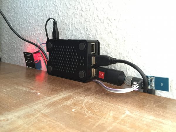
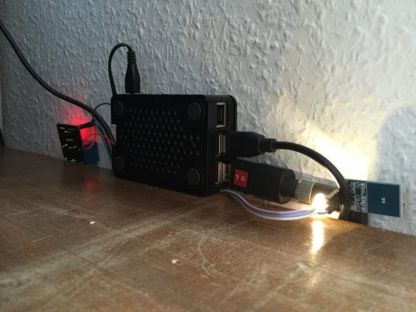
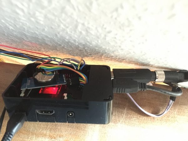
Hardware Setup
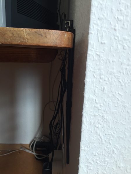
Turn the Raspi off, remove all the cables!
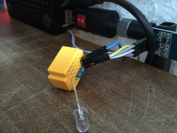
Wiring the Relay, the Touch Sensor, and the LED
The scripts here use relay 2, as this is the local setup. YMMV. The following GPIO.BCM configuration is used in the scripts:
- GPIO.BCM 19 # the touch sensor
- GPIO.BCM 20 # the relay
- GPIO.BCM 26 # the LED
Do Not Forget
- The relay will likely need to be connected to 5 V Power.
- The appropriate resistors for all the pins used, as 5 V (not 3.3 V) are used, so Raspi may be damaged otherwise.
Wiring the RTC (optional)
- 3.3 V
- GPIO.BCM 2 (SDA)
- GPIO.BCM 3 (SCL)
- Ground
Do Not Forget
- hwclock -w
Connecting the Relay to the Mains
Be extra careful, electricity could kill you.
- Remove the computer power chord from the mains for real.
- Cut through the outer insulation of the computer power chord, about 10–15 cm (4–5 in.) long.
- Make sure you haven’t damaged the inner cables.
- Cut the inner blue cable in two, remove some of the insulation at its ends.
- Connect both ends of the blue cable to the relay
- Plug the cord into the mains.
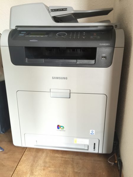
Alternative Power Strip Setup
Instead of a power cord, you can use a power strip and thus control several devices at once. For example, plugging a small Wi-Fi router into that power strip, configuring it as a bridge, and connecting it to a network (LAN) MFP, would make it a fine WLAN MFP. You may even scan over WLAN (tested with Samsung Mobile Print on iOS and Samsung CLX-6220FX).
Finally…
… enjoy!
Comments are closed.